
By Phodal (Follow Me: 微博、知乎、SegmentFault)
我的其他电子书:
微信公众号
当前为预览版,在使用的过程中遇到任何遇到请及时与我联系。阅读过程中问题,不烦在GitHub上提出来: Issues
阅读过程中遇到语法错误、拼写错误、技术错误等等,不烦来个Pull Request,这样可以帮助到其他阅读这本电子书的童鞋。
最近这些日子里,当我和女朋友搬到了新的合租屋里,有了更大的空间——可以再次折腾硬件。便开始去玩一些硬件家居相关的内容,也顺便接上了 Amazon Echo、小米传感器、Broadlink、ESP8266 等等的硬件。
再加上正在编写的『玩点什么』网站,便也想整理一下硬件相关的资料。想着想着,便有了这一系列的电子书。
这是一本写给软件工程师看的硬件指南。
黄峰达(Phodal Huang)是一个创客、工程师、咨询师和作家。他毕业于西安文理学院电子信息工程专业,现作为一个咨询师就职于 ThoughtWorks 深圳。长期活跃于开源软件社区 GitHub,目前专注于物联网和前端领域。
作为一个开源软件作者,著有 Growth、Stepping、Lan、Echoesworks 等软件。其中开源学习应用 Growth,广受读者和用户好评,可在 APP Store 及各大 Android 应用商店下载。
作为一个技术作者,著有《自己动手设计物联网》(电子工业出版社)、《全栈应用开发:精益实践》(电子工业出版社,正在出版)。并在 GitHub 上开源有《Growth: 全栈增长工程师指南》、《GitHub 漫游指南》等七本电子书。
作为技术专家,他为英国 Packt 出版社审阅有物联网书籍《Learning IoT》、《Smart IoT》,前端书籍《Angular 2 Serices》、《Getting started with Angular》等技术书籍。
他热爱编程、写作、设计、旅行、hacking,你可以从他的个人网站:https://www.phodal.com/ 了解到更多的内容。
其它相关信息:
当前为预览版,在使用的过程中遇到任何问题请及时与我联系。阅读过程中的问题,不妨在GitHub上提出来: Issues
阅读过程中遇到语法错误、拼写错误、技术错误等等,不妨来个Pull Request,这样可以帮助到其他阅读这本电子书的童鞋。
其他电子书:
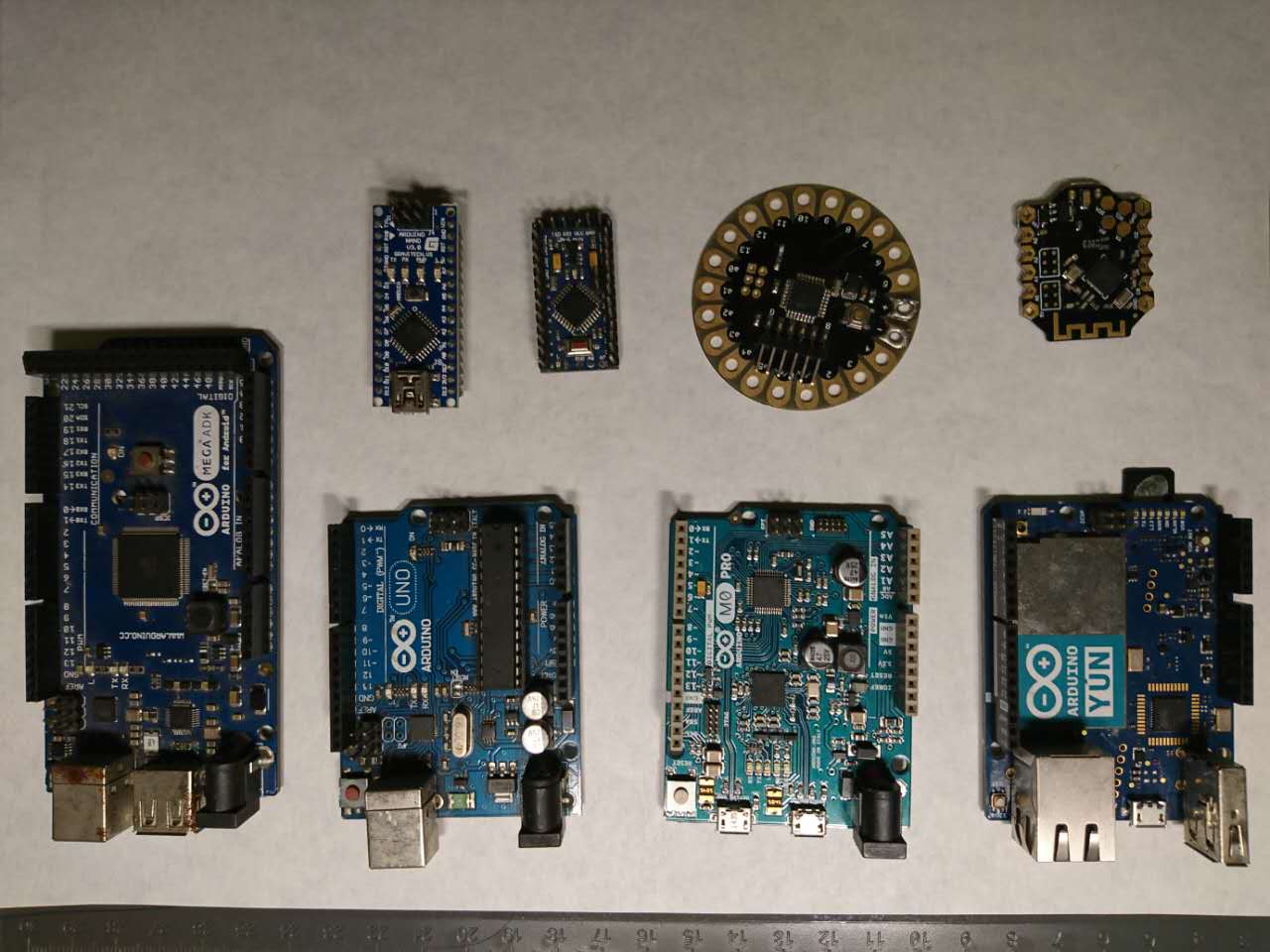
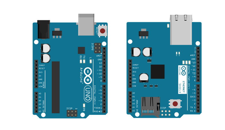
在这一系列的文章里,我们使用三个主要的开发板:
这三个硬件分别代表着,三种不同类型的硬件爱好者的开发板。
Arduino,是一个开放源代码的单片机微控制器,它使用了Atmel AVR单片机,采用了开放源代码的软硬件平台,建构于简易输出/输入(simple I/O)接口板,并且具有使用类似Java、C语言的Processing/Wiring开发环境。1
其包含了以下的特性2:
当然,其最大的特色是,完善的社区及生态系统。几乎我们能想到的 Arduino 相关的创意,都可以在网上找到。如果没有的话,那么可能是你的创意不适合用于 Arduino。
Arduino 已然有一系列的相关硬件,就目前而言,最广泛的开发板,或者说是标准开发板是 Arduino UNO。
TODO: 相关 Arduino 硬件介绍
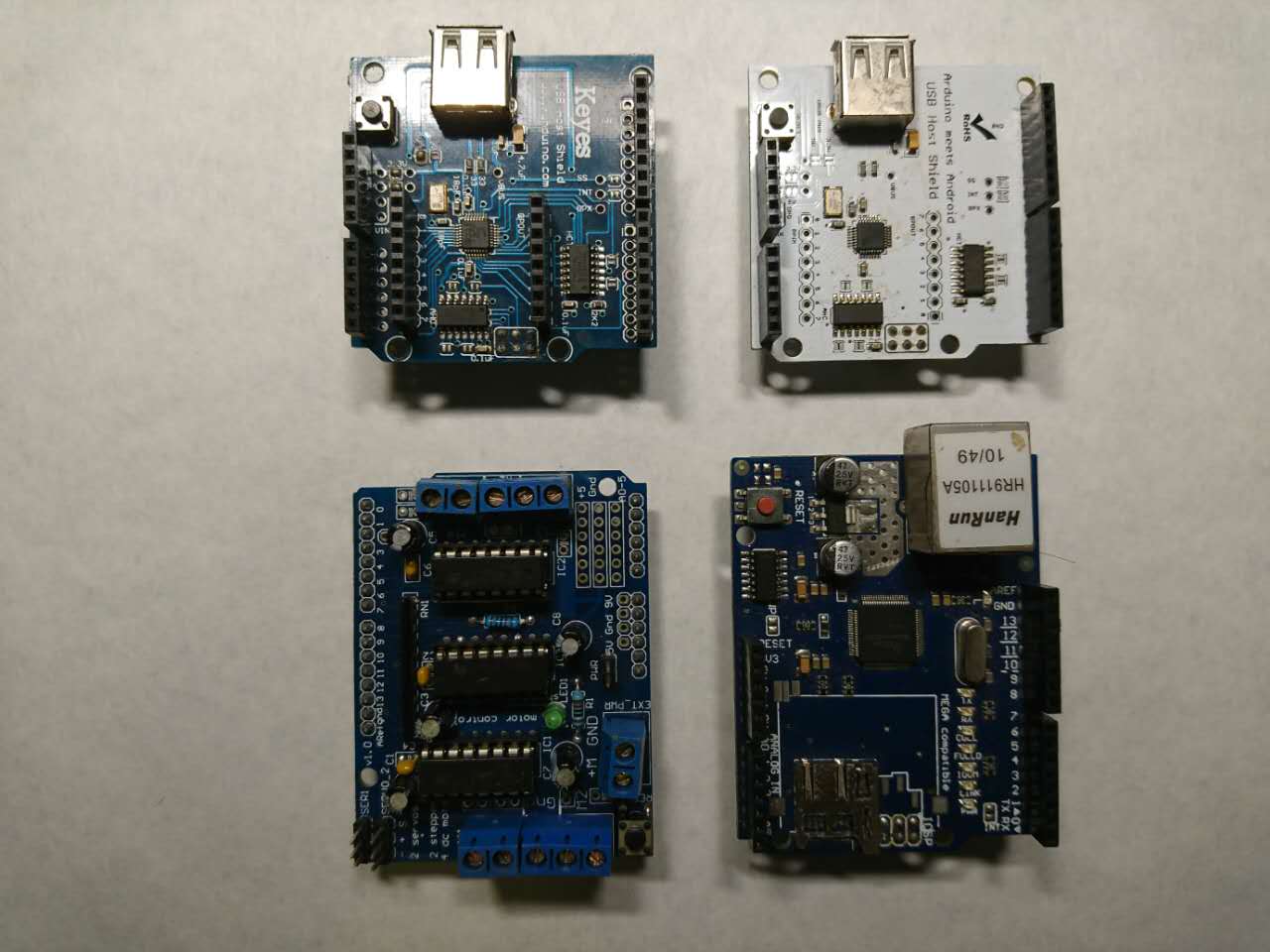
Arduino 最吸引人的是开创性的引入电子积木的概念,即开发板的扩展板可以直接叠加在开发板上使用,而无需额外的硬件。
TODO: 扩展板介绍。
Arduion IDE 基于 Processing 开发环境而开发的。
引脚
模电
数电
电流、电阻、电压
etc..
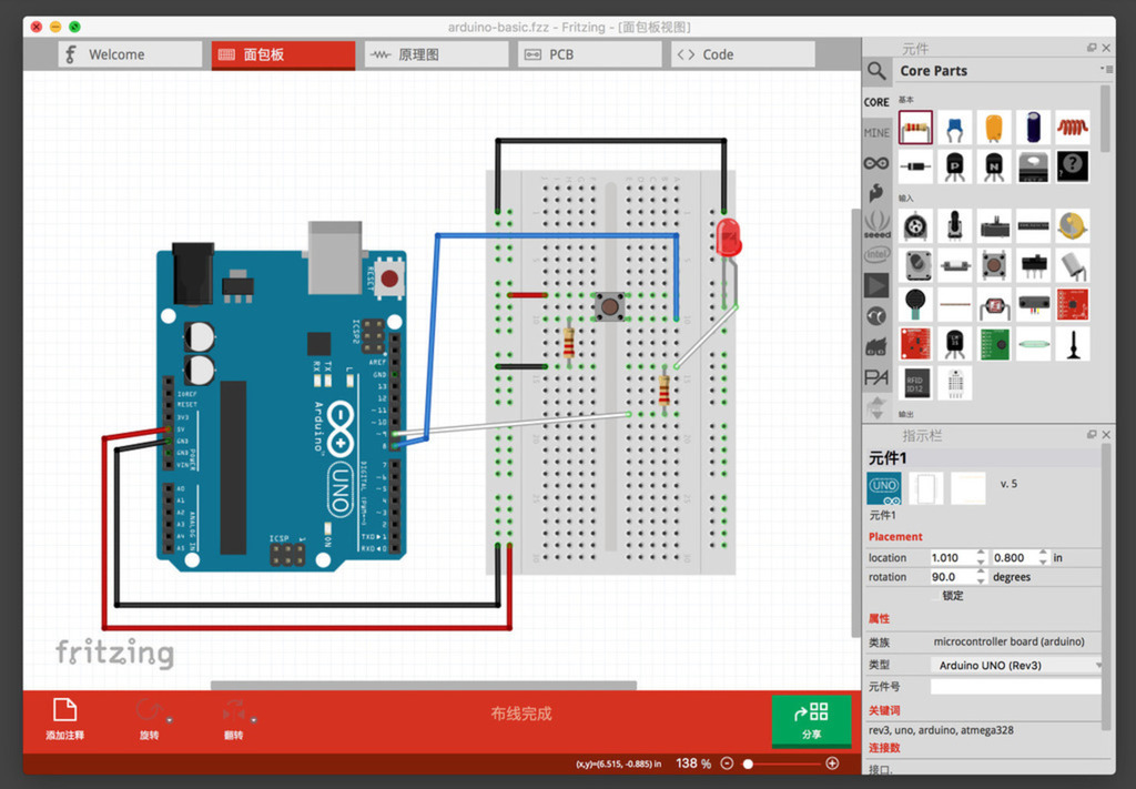
为了更好的向读者展示硬件连线,我们将使用 Fritzing 汇制硬件电路图。
Fritzing 是一个开源的硬件计划(initiative),它可以使电子元件变成任何人的创意素材。Fritzing 提供一个软件工具、一个社区网站,以及本着 Processing 和 Arduino 精神的服务,培养创造性的生态系统,允许用户记录他们的原型,与他人分享、用于课堂上的电子相关教学,以及布局和制造专业的pcb。
Fritzing 的官网是:http://fritzing.org/。
因此,在开始之前我们需要在 Fritzing 的官网下载 Fritzing。当前它可以支持主流的操作系统:Windows、Linux、macOS,当然如果你想自己从源码编译一个 Fritzing,那也是可以的。除了中文和英语外,它还支持其它 17 种语言。
在其官网,除了能下载到该软件,还可以看到其它用户上传、汇制的 Fritzing 电路图等,它们可以免费下载,并引用到你的项目中。
LCEDA
Nokia 5110
温度、红外、距离、土壤
Input -> MCU -> Output
蓝牙、有线、
专用协议,blabla
幸运的是,今天对硬件编程已经有了更多的方式,可以使用更高级的语言。除了在 Arduion 上使用 Processing 语言(可以视为 C)进行编程,还可以使用 JavaScript 等语言。我们会在后面的介绍:如何使用这些高级的语言来编程。
Arduino IDE 默认会安装相应环境的包,如果你的开发板不在这些环境里,如你使用的是 Arduino M0 开发板。那么,系统可能会检测出来,并自动为你安装相应的环境,如下图所示。
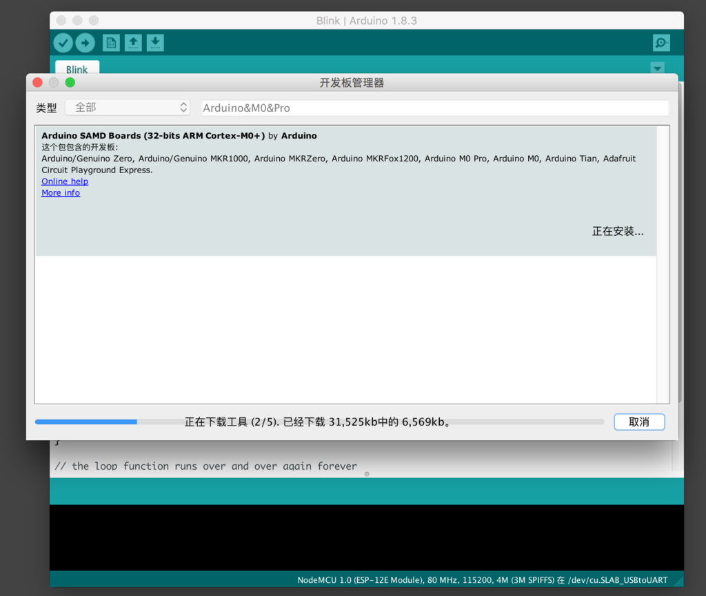
注意:安装过程中会下载一系列的工具,在这个过程里,可能会遇到一些“网络问题”。请尝试更换网络,或直到到“墙”的那外一边。
对于非官方的开发板来说,则需要开发者自己手动通过『开发板管理器』来安装,如 ESP8266 开发板。
与桌面端使用 print、puts、console.log 来输出 Hello, world 不同的是,点亮一个 LED 是 电子世界的 Hello, world。
在硬件世界里,没有 stdlib.h 这样的库,对于多数嵌入式系统来说,也没有屏幕。在这个时候,想要知道设备的状态,最简单的方式就是 LED。常见的,如路由器、电视等家电电器上的灯,都是嵌入式设备的状态。
官方的 Blink 示例如下:
void setup() {
  // initialize digital pin LED_BUILTIN as an output.
  pinMode(LED_BUILTIN, OUTPUT);
}

// the loop function runs over and over again forever
void loop() {
  digitalWrite(LED_BUILTIN, HIGH);   // turn the LED on (HIGH is the voltage level)
  delay(1000);                       // wait for a second
  digitalWrite(LED_BUILTIN, LOW);    // turn the LED off by making the voltage LOW
  delay(1000);                       // wait for a second
}
接下来,要做的事情就比较简单了。从工具( Tools )中选择对应的开发板和端口,如下图所示:

我这里使用设置是 Arduino M0 Pro,对应的端口是:/dev/tty.usbmodem1412。
对于 Windows 用户来说,则是 COM 口——从设备管理器中找到对应的端口。
然后点击菜单中的 -> 号,即上传(Upload,又可以称为烧录)。

再看看你的 Arduion,就发现上面的 LED 正在闪烁——一秒开一秒关。
源码中的:
int main(void)
{
    init();
    setup();
    for(;;)
        loop();

    return 0;
}GOAL
SMART 原则
仍然采用的是官方的示例:
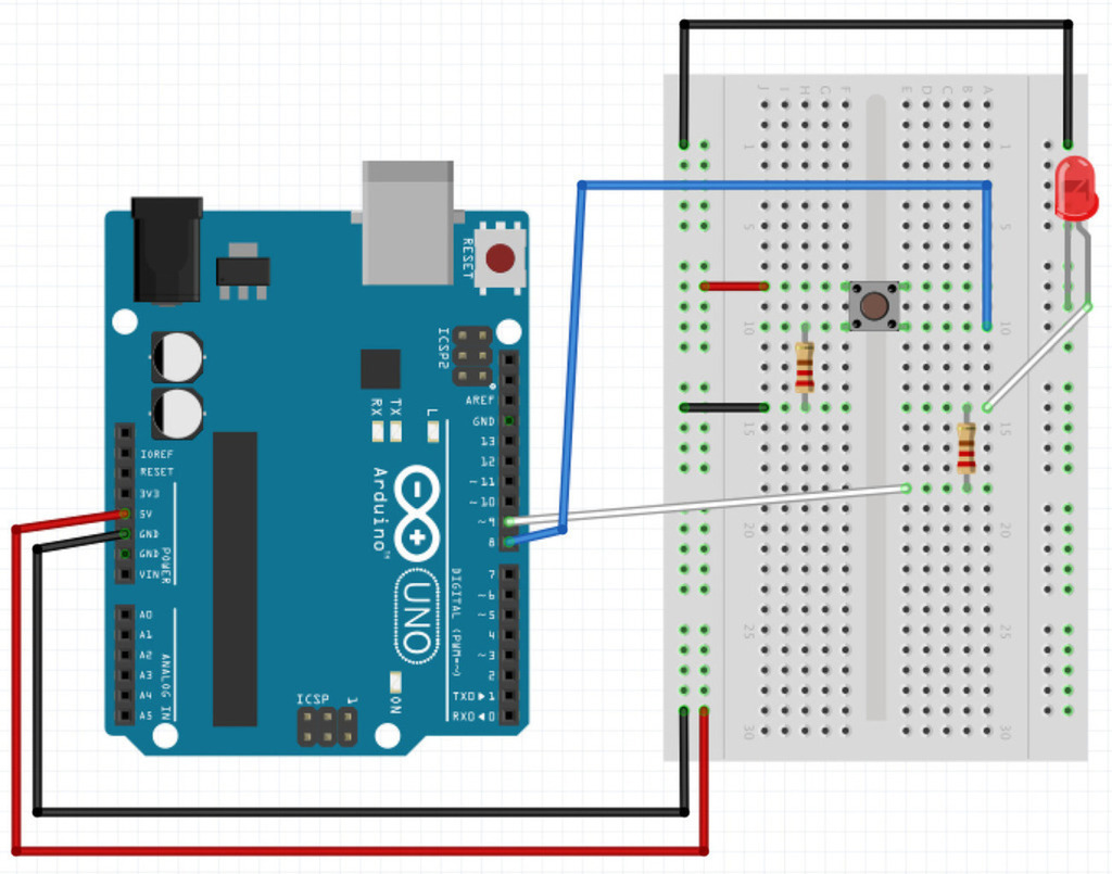
官方示例(Digital Read Serial)代码:
// digital pin 2 has a pushbutton attached to it. Give it a name:
int pushButton = 2;

// the setup routine runs once when you press reset:
void setup() {
  // initialize serial communication at 9600 bits per second:
  Serial.begin(9600);
  // make the pushbutton's pin an input:
  pinMode(pushButton, INPUT);
}

// the loop routine runs over and over again forever:
void loop() {
  // read the input pin:
  int buttonState = digitalRead(pushButton);
  // print out the state of the button:
  Serial.println(buttonState);
  delay(1);        // delay in between reads for stability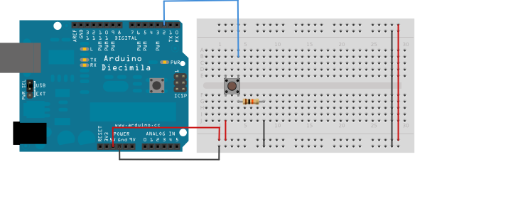
}使用 Fritzing 画板时
我们所需要的连线图
传感器是一种物理装置或生物器官,能够探测、感受外界的信号、物理条件(如光、热、湿度)或化学组成(如烟雾),并将探知的信息传递给其他装置或器官。“传感器”在新韦式大词典中定义为:“从一个系统接受功率,通常以另一种形式将功率送到第二个系统中的器件”。根据这个定义,传感器的作用是将一种能量转换成另一种能量形式,所以不少学者也用“换能器-Transducer”来称谓“传感器-Sensor”。[^wiki_sensor]
[^wiki_sensor] : https://zh.wikipedia.org/wiki/%E4%BC%A0%E6%84%9F%E5%99%A8
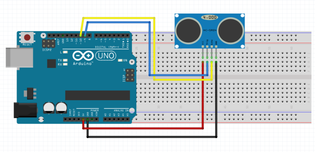
使用到库:[NewPing],GitHub 地址:https://github.com/PaulStoffregen/NewPing
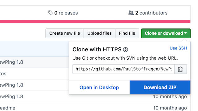
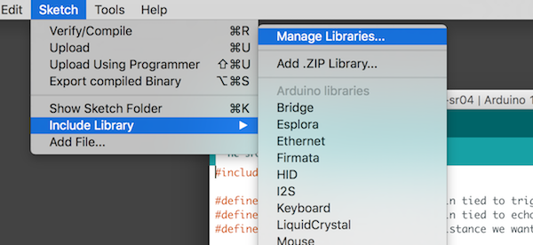
添加库

#include <NewPing.h>

#define TRIGGER_PIN  12  // Arduino pin tied to trigger pin on the ultrasonic sensor.
#define ECHO_PIN     11  // Arduino pin tied to echo pin on the ultrasonic sensor.
#define MAX_DISTANCE 200 // Maximum distance we want to ping for (in centimeters). Maximum sensor distance is rated at 400-500cm.

NewPing sonar(TRIGGER_PIN, ECHO_PIN, MAX_DISTANCE); // NewPing setup of pins and maximum distance.

void setup() {
  Serial.begin(115200); // Open serial monitor at 115200 baud to see ping results.
}

void loop() {
  delay(50);                     // Wait 50ms between pings (about 20 pings/sec). 29ms should be the shortest delay between pings.
  Serial.print("Ping: ");
  Serial.print(sonar.ping_cm()); // Send ping, get distance in cm and print result (0 = outside set distance range)
  Serial.println("cm");
}
项目地址:Adafruit PCD8544
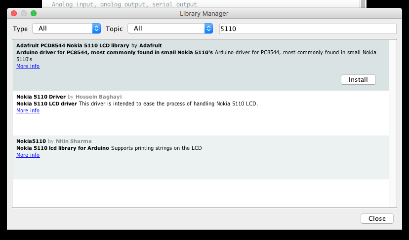
一般来说,在安装完库后,都会有对应的示例。但是,这里的示例,稍微有一些复杂。
#include <Arduino.h>

#include <SPI.h>
#include <Adafruit_GFX.h>
#include <Adafruit_PCD8544.h>

// Pins
const int8_t RST_PIN = D2;
const int8_t CE_PIN = D1;
const int8_t DC_PIN = D6;
//const int8_t DIN_PIN = D7;  // Uncomment for Software SPI
//const int8_t CLK_PIN = D5;  // Uncomment for Software SPI
const int8_t BL_PIN = D0;


// Software SPI with explicit CE pin.
// Adafruit_PCD8544 display = Adafruit_PCD8544(CLK_PIN, DIN_PIN, DC_PIN, CE_PIN, RST_PIN);

// Software SPI with CE tied to ground. Saves a pin but other pins can't be shared with other hardware.
// Adafruit_PCD8544(int8_t CLK_PIN, int8_t DIN_PIN, int8_t DC_PIN, int8_t RST_PIN);

// Hardware SPI based on hardware controlled SCK (SCLK) and MOSI (DIN) pins. CE is still controlled by any IO pin.
// NOTE: MISO and SS will be set as an input and output respectively, so be careful sharing those pins!
Adafruit_PCD8544 display = Adafruit_PCD8544(DC_PIN, CE_PIN, RST_PIN);

void setup() {
  Serial.begin(9600);
  Serial.println("\n\nWeMos D1 Mini + Nokia 5110 PCD8544 84x48 Monochrome LCD\nUsing Adafruit_PCD8544 and Adafruit_GFX libraries\n");

  // Turn LCD backlight on
  pinMode(BL_PIN, OUTPUT);
  digitalWrite(BL_PIN, HIGH);

  display.begin();
  display.setContrast(60);  // Adjust for your display
  Serial.println("Show Adafruit logo bitmap");

  // Show the Adafruit logo, which is preloaded into the buffer by their library
  // display.clearDisplay();
  delay(2000);

  display.clearDisplay();
  display.setTextSize(1);
  display.setTextColor(BLACK);
  display.setCursor(0,0);
  display.println("Hello, world!");
  display.display();
}

void loop() {
}Bluno 等自带蓝牙的开发板
React Native / Cordova ???
I don’t know
/**
 * BasicHTTPClient.ino
 *
 *  Created on: 24.05.2015
 *
 */

#include <Arduino.h>

#include <ESP8266WiFi.h>
#include <ESP8266WiFiMulti.h>

#include <ESP8266HTTPClient.h>

#define USE_SERIAL Serial

ESP8266WiFiMulti WiFiMulti;

void setup() {

    USE_SERIAL.begin(115200);
   // USE_SERIAL.setDebugOutput(true);

    USE_SERIAL.println();
    USE_SERIAL.println();
    USE_SERIAL.println();

    for(uint8_t t = 4; t > 0; t--) {
        USE_SERIAL.printf("[SETUP] WAIT %d...\n", t);
        USE_SERIAL.flush();
        delay(1000);
    }

    WiFiMulti.addAP("SSID", "PASSWORD");

}

void loop() {
    // wait for WiFi connection
    if((WiFiMulti.run() == WL_CONNECTED)) {

        HTTPClient http;

        USE_SERIAL.print("[HTTP] begin...\n");
        // configure traged server and url
        //http.begin("https://192.168.1.12/test.html", "7a 9c f4 db 40 d3 62 5a 6e 21 bc 5c cc 66 c8 3e a1 45 59 38"); //HTTPS
        http.begin("http://192.168.1.12/test.html"); //HTTP

        USE_SERIAL.print("[HTTP] GET...\n");
        // start connection and send HTTP header
        int httpCode = http.GET();

        // httpCode will be negative on error
        if(httpCode > 0) {
            // HTTP header has been send and Server response header has been handled
            USE_SERIAL.printf("[HTTP] GET... code: %d\n", httpCode);

            // file found at server
            if(httpCode == HTTP_CODE_OK) {
                String payload = http.getString();
                USE_SERIAL.println(payload);
            }
        } else {
            USE_SERIAL.printf("[HTTP] GET... failed, error: %s\n", http.errorToString(httpCode).c_str());
        }

        http.end();
    }

    delay(10000);
}https://github.com/tuanpmt/esp_mqtt
#include <ESP8266WiFi.h>
#include <ESP8266WebServer.h>

ESP8266WebServer server(80);

void setup() {

  Serial.begin(115200);
  WiFi.begin("Network name", "Password");  //Connect to the WiFi network

  while (WiFi.status() != WL_CONNECTED) {  //Wait for connection
    delay(500);
    Serial.println("Waiting to connect…");
  }

  Serial.print("IP address: ");
  Serial.println(WiFi.localIP());  //Print the local IP

  server.on(" / other", []() {   //Define the handling function for the path

    server.send(200, "text / plain", "Other URL");

  });

  server.on(" / ", handleRootPath);    //Associate the handler function to the path
  server.begin();                                       //Start the server
  Serial.println("Server listening");
}

void loop() {
  server.handleClient();
}

void handleRootPath() {
  server.send(200, "text/plain", "Hello world");
}